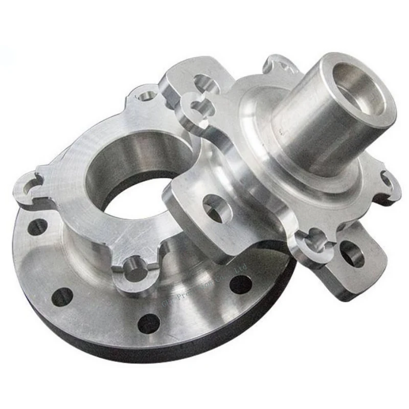
Flanged Sleeve Setup Example
CNC Turn-Mill Setup Example: Flanged Sleeve
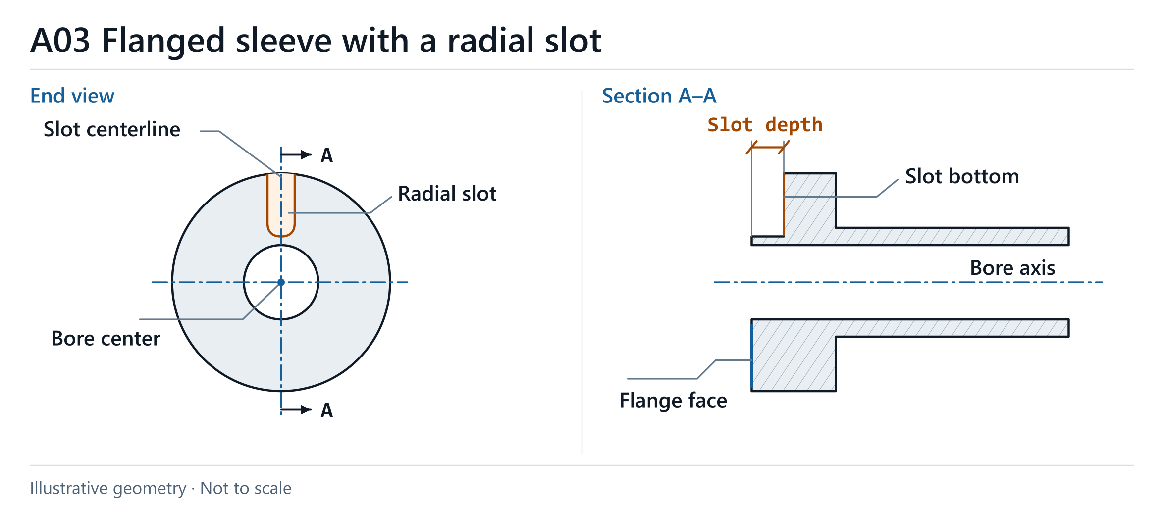
This flanged sleeve example shows how a turned bore and a flange face guide the machining and inspection of a radial slot.
- Process
- Turning and milling, with setup chosen after review
- Материалы
- Material and stock form per drawing
- Количество
- Confirm required quantities
- Inspection
- Slot position from the bore axis and depth from the flange face
Product Overview
Consider an illustrative flanged sleeve with a turned bore and a radial slot. The bore establishes the reference axis for slot location, and the flange face provides the reference for slot depth. The drawing, tool access and workpiece support guide the choice of setup.
Key Features
- The turned bore establishes the datum axis for the radial slot.
- The drawing specifies the relationship between the slot centerline and the bore axis.
- The designated flange face is the reference for slot depth.
Manufacturing Considerations
- Driven tooling may allow the slot to be machined in the original clamping if cutter access and workpiece support are suitable.
- A separate milling setup may improve access or stability. In that case, re-establish the finished bore axis and the flange reference face.
- Check the effects of relocation on slot position and flange seating on slot depth when choosing the setup.
Quality Control & Inspection
- After the relevant operations and fixture release, check slot position relative to the specified bore datum axis.
- Check slot depth from the designated flange face in the specified delivery condition.
Specifications to Confirm
| Bore datum | Identify the bore axis that controls slot position. |
|---|---|
| Flange reference | Identify the face from which slot depth is specified. |
| Setup planning | Review cutter access and support for driven tooling or separate milling. |
| Inspection condition | Check the required slot features after fixture release where specified. |
Assembly Considerations
Bore Alignment
Confirm the required relationship between the slot centerline and the bore axis where the drawing specifies it.
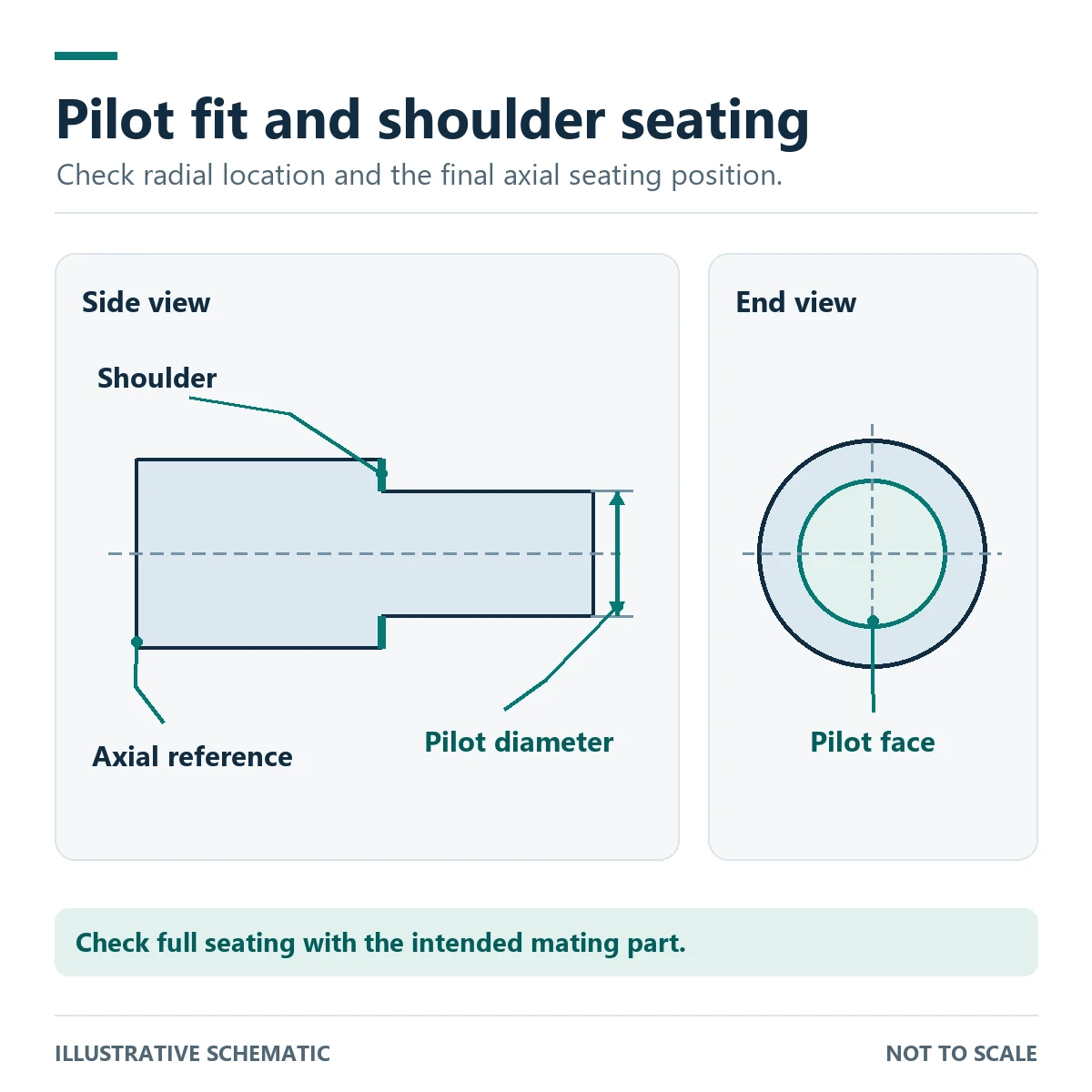
Flange Seating
Identify the flange face used to establish slot depth.

Запросите предложение на обработку на ЧПУ
Share your drawing, материал, quantity and critical feature requirements. We will review the appropriate machining route, any necessary secondary operations and the proposed inspection scope.