Valve & Flow-Control Components
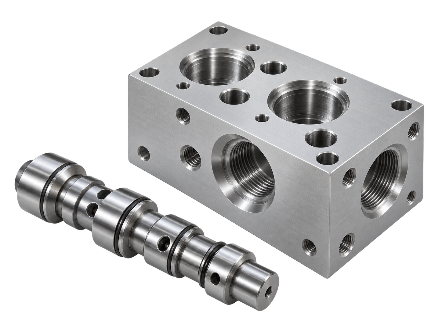
Valve bodies · Valve spools · Manifolds
Typical considerations include bore geometry, internal passages, intersecting holes, sealing interfaces and the relationships between controlled features.


Precision machining / Fluid power
Drawing-based CNC machining for valve, manifold and actuator components.
Hydraulic and pneumatic parts often depend on the relationships between bores, sealing surfaces, mating features and internal passages.
Component types
GPT Precision reviews drawing-based enquiries for a range of hydraulic and pneumatic components.
Valve bodies · Valve spools · Manifolds
Typical considerations include bore geometry, internal passages, intersecting holes, sealing interfaces and the relationships between controlled features.
Piston rods · End caps · Actuator housings
Reviews may involve controlled diameters, shaft and bore fits, alignment, surface condition and mounting interfaces.
Fittings · Filter housings · Seal retainers
Important features may include threads, connection surfaces, seal grooves, mating faces and controlled internal edges.
Component examples indicate the types of enquiries considered. Machining feasibility and supply scope are confirmed for each drawing.
Drawing-led review
GPT Precision reviews machining enquiries for valve bodies, manifolds, actuator components and related precision parts. We evaluate critical geometry, material condition, intended operating conditions and inspection requirements against your drawings before confirming the manufacturing scope.
Define bore and shaft fits, seal groove dimensions, surface roughness, datum references and any specified geometric tolerances.
These requirements help establish machining and inspection plans for the features that control assembly, alignment and sealing.
Show passage diameters, depths, intersecting holes, blind ends and restricted-access features on your drawings.
Drilling methods, tool access, internal deburring and available inspection methods are evaluated against the actual geometry.
Specify the material grade and condition, operating pressure range, working medium, temperature and any corrosion or wear concerns.
These details provide context for reviewing machining suitability, material requirements and applicable surface treatments.
Identify cross-hole intersections, internal edges and passages that are sensitive to burrs or contamination.
Specify any required limits for particles, residues or edge conditions. Deburring, cleaning and verification requirements are reviewed and agreed as part of the supply scope.
Process planning
CNC milling, turning and drilling are evaluated according to the part geometry and critical features.
Where deep-hole drilling, internal or external grinding, or surface treatment is required, the proposed process and available supply scope are confirmed during technical review.
Carbon and alloy steels, stainless steel, aluminum alloys and brass may be considered depending on the application.
Provide the specified material grade, condition and applicable standard, along with any restrictions on substitutions.
Material availability, machining suitability and finishing requirements are reviewed for each project.
Define the acceptance criteria
Inspection planning begins with the dimensions and feature relationships that matter to the finished part.
Identify critical tolerances, datum references, surface roughness requirements and the inspection records needed for acceptance.
Leak, pressure and cleanliness testing must be specified separately. Methods, acceptance criteria, reporting requirements and responsibilities are confirmed where these tests form part of the agreed scope.
Sealing performance depends on the complete assembly, including mating components, seals and operating conditions. Dimensional acceptance of an individual part does not, by itself, establish system-level performance.
Start your enquiry
Send your current 2D drawings and available 3D CAD files, together with:
We will review the available information to establish machining feasibility, manufacturing scope and quotation requirements.
Drawings and CAD files may also be sent to
sales@precisiontoolingchina.com.