Illustrative Two-Pocket Plate
CNC Milled Part Examples
Understanding how machined pocket floors, ribs and mounting faces affect installed assembly clearance.
- Process
- CNC milling of pockets, a center rib and a mounting face
- Materials
- Material and finish per drawing
- Quantity
- Confirm required quantities
- Inspection
- Installed clearance at the pocket floors and rib
Product Overview
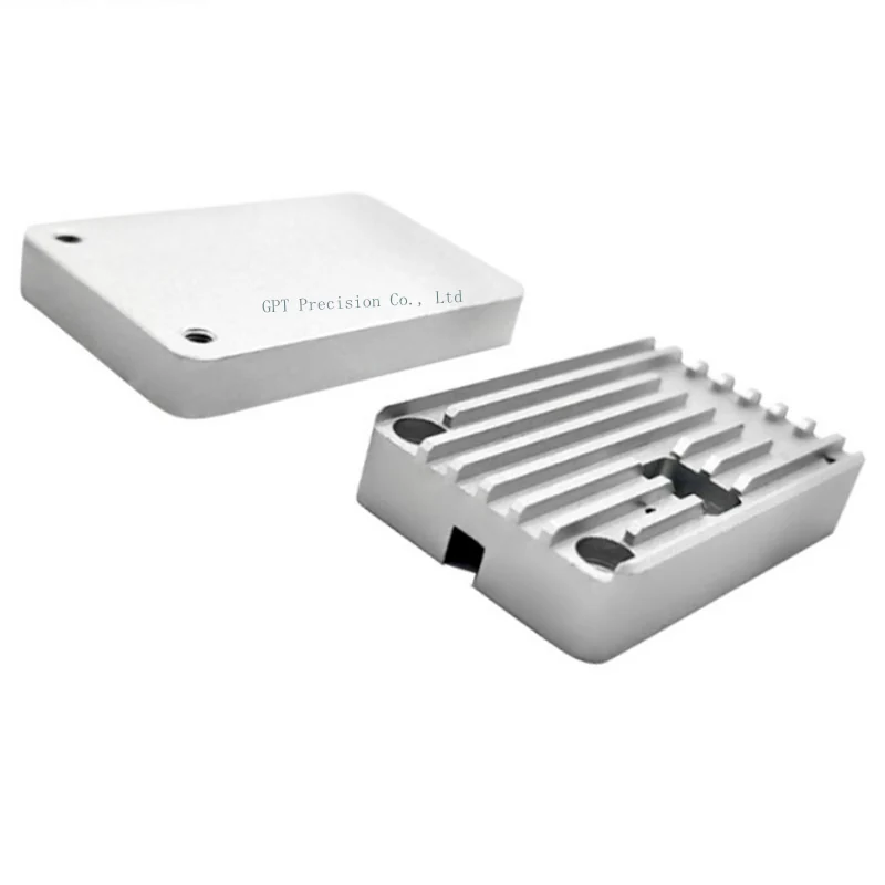
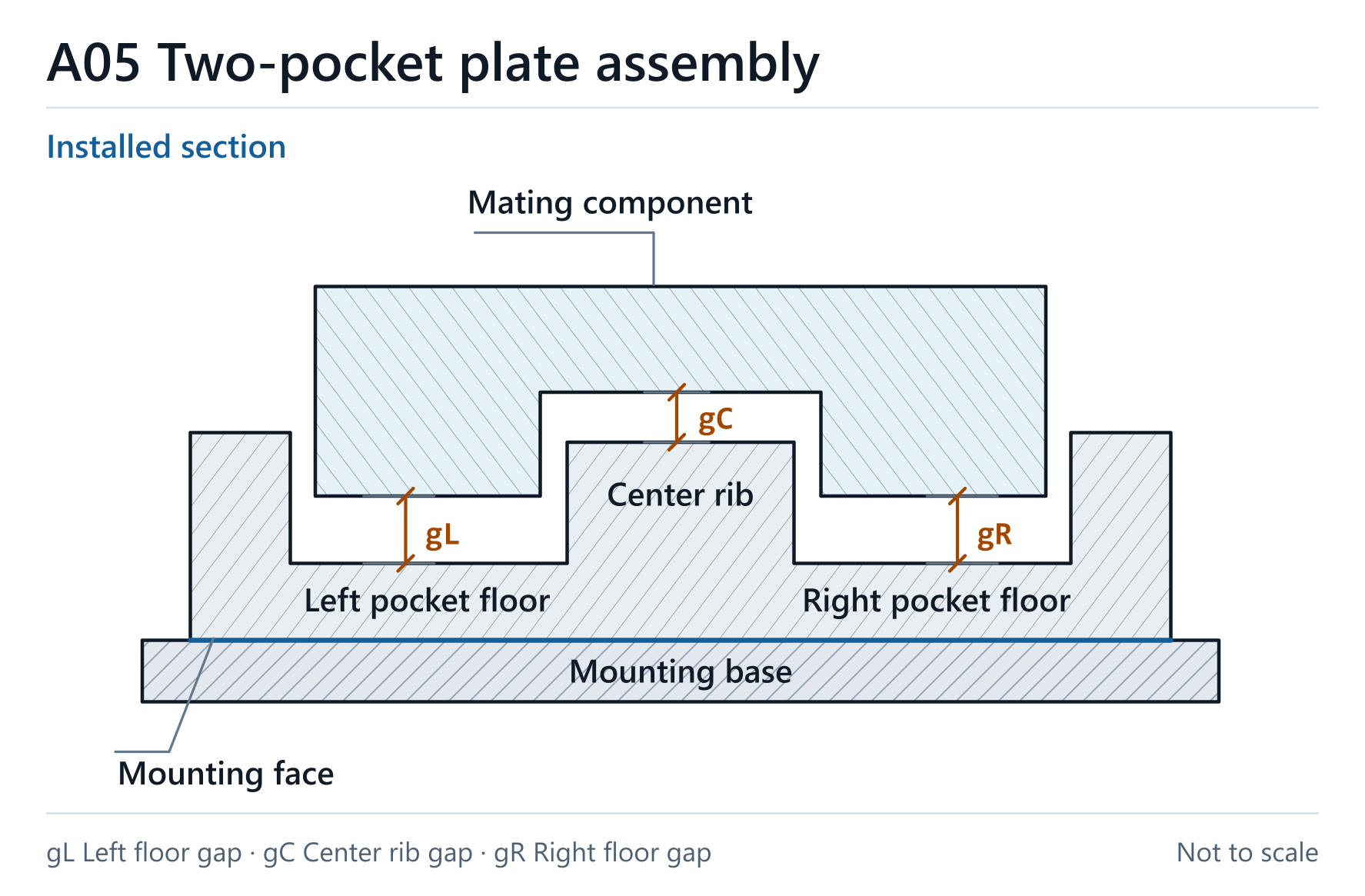
Consider an illustrative CNC-milled plate containing two pockets separated by a raised center rib.
The underside of the plate seats against a mounting base, while the mating component extends into the pockets and passes over the rib.
The available clearance depends on the relationship between the mating component and the machined surfaces.
Key Features
- Two recessed pockets are separated by a raised center rib.
- The underside seats against the mounting base and establishes the installed height in this example.
- The mating component extends into both pockets and passes over the rib.
Manufacturing Considerations
- Relate pocket-floor and rib heights to the drawing datum system, including the mounting reference where it controls installed height.
- Check the remaining floor thickness separately where the drawing specifies a minimum.
Quality Control & Inspection
- Verify the pocket-floor and rib heights from the specified reference system in the final surface condition.
- Where a functional check is agreed, seat the finished part against the specified reference or mating component and assess the required clearances.
Specifications to Confirm
| Mounting datum | Use the specified underside or mounting reference for installed height. |
|---|---|
| Pocket floors and rib | Define the required heights relative to the assembly datum system. |
| Minimum clearance | Evaluate dimensional limits and location variation at each potential contact point. |
| Floor thickness | Check separately where a minimum thickness is specified. |
Assembly Considerations
Seating Face
Establish installed height from the specified mounting reference. Check clearance from that reference even when pocket depth is dimensioned from an upper face.
Pocket Clearance
At each floor, compare the lowest permitted mating surface with the highest permitted pocket floor from a shared reference. Include relevant datum and location variation.
Rib Clearance
Check the lowest permitted mating surface against the highest permitted rib top in the installed position.
Related Products

Discuss Your Milled Component
Provide the part drawing and relevant assembly section, highlighting minimum gaps, seating faces and critical locating features. We can review how the finished dimensions relate to the intended assembly.